


So at least on this level, due to the lack of the TFT, the LPD could potentially be much cheaper than the Eink.
This is my adventure with the screen so far. Still not sure what I want to do with the screen, let me know if you have any ideas. In any case, thanks for reading!
This is my adventure with the screen so far. Still not sure what I want to do with the screen, let me know if you have any ideas. In any case, thanks for reading!

April 6, 2025 at 12:47 AM
So at least on this level, due to the lack of the TFT, the LPD could potentially be much cheaper than the Eink.
This is my adventure with the screen so far. Still not sure what I want to do with the screen, let me know if you have any ideas. In any case, thanks for reading!
This is my adventure with the screen so far. Still not sure what I want to do with the screen, let me know if you have any ideas. In any case, thanks for reading!
Eink is much slower, typically requiring 100ms+ for it to fully change color. The presence of TFT (+capacitor) ensures the pixel keeps getting driven even when the line is not currently being scanned. If without, a 320x240 panel would take 0.1*240=24 seconds to update!
April 6, 2025 at 12:46 AM
Eink is much slower, typically requiring 100ms+ for it to fully change color. The presence of TFT (+capacitor) ensures the pixel keeps getting driven even when the line is not currently being scanned. If without, a 320x240 panel would take 0.1*240=24 seconds to update!
Another characteristic making it possible to drive without TFT is it's fast. As fast as 0.2ms from black to white. Without TFT, the pixel is only driven when the line is scanned. With a 0.2ms line time, a 320x240 panel takes a quite reasonable 0.2*240=48 ms to update
April 6, 2025 at 12:46 AM
Another characteristic making it possible to drive without TFT is it's fast. As fast as 0.2ms from black to white. Without TFT, the pixel is only driven when the line is scanned. With a 0.2ms line time, a 320x240 panel takes a quite reasonable 0.2*240=48 ms to update
According to the paper, the LPD screen shouldn't respond to the 40V voltage. (Though based on my tests it still does. The threshold is more like 20V rather than 40V). But the important thing is it could withstand non-zero OFF voltage. Eink starts to respond at even 0.1V.
April 6, 2025 at 12:45 AM
According to the paper, the LPD screen shouldn't respond to the 40V voltage. (Though based on my tests it still does. The threshold is more like 20V rather than 40V). But the important thing is it could withstand non-zero OFF voltage. Eink starts to respond at even 0.1V.
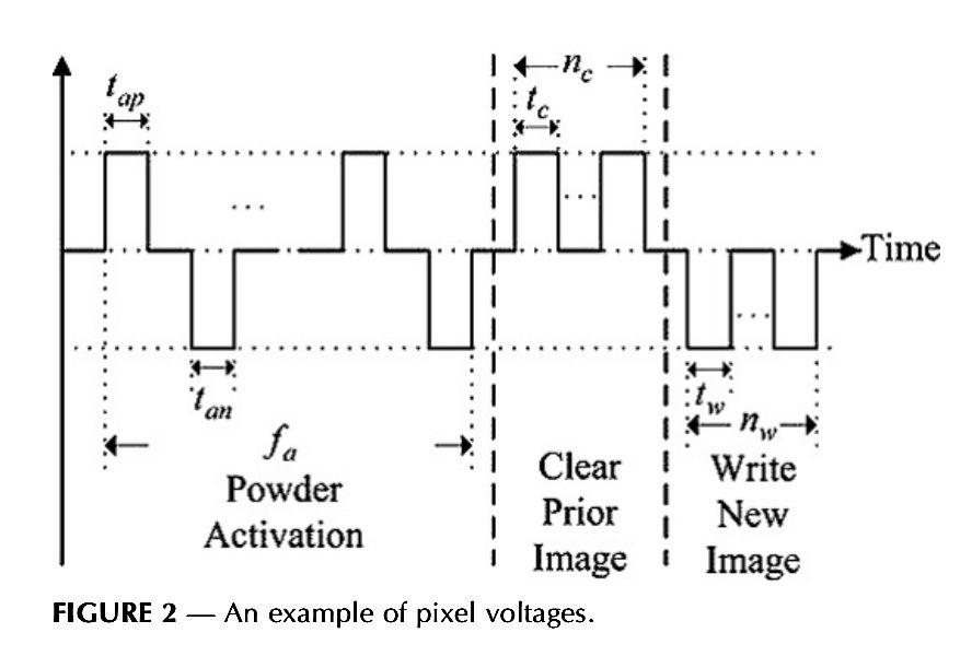
Taking the driving waveform from the paper, up to +/-40V are applied to non-selected pixels (pixels that shouldn't change color during the scan). This is what happens when the screen doesn't have TFT: pixels cannot be fully turned OFF, there is always a voltage on the pixel.
April 6, 2025 at 12:45 AM
Taking the driving waveform from the paper, up to +/-40V are applied to non-selected pixels (pixels that shouldn't change color during the scan). This is what happens when the screen doesn't have TFT: pixels cannot be fully turned OFF, there is always a voltage on the pixel.
But TFTs are expensive. The cost is okay for mass-produced screens (like >10K pcs per month), but prohibitive for smaller quantities. This is where LPD shines, it doesn't require TFT because it has a threshold: it doesn't respond to low voltages.
April 6, 2025 at 12:45 AM
But TFTs are expensive. The cost is okay for mass-produced screens (like >10K pcs per month), but prohibitive for smaller quantities. This is where LPD shines, it doesn't require TFT because it has a threshold: it doesn't respond to low voltages.
I realized I forgot to mention the advantage it has over Eink: it doesn't require TFT. TFT screens add tiny transistors under each pixel, so they can be switched ON/ OFF in a matrix without having to worry about issues like ON/ OFF voltage ratio like what I just discussed.
April 6, 2025 at 12:45 AM
I realized I forgot to mention the advantage it has over Eink: it doesn't require TFT. TFT screens add tiny transistors under each pixel, so they can be switched ON/ OFF in a matrix without having to worry about issues like ON/ OFF voltage ratio like what I just discussed.
But it seems to be almost impossible for me to get a Pricer ESL from that era, or see any of those LPD demo machines (linked below) IRL. So maybe I will never know.
www.youtube.com/watch?v=MDvO...
www.youtube.com/watch?v=MDvO...
April 6, 2025 at 12:23 AM
But it seems to be almost impossible for me to get a Pricer ESL from that era, or see any of those LPD demo machines (linked below) IRL. So maybe I will never know.
www.youtube.com/watch?v=MDvO...
www.youtube.com/watch?v=MDvO...
This is basically what I have got with this screen so far. If possible I would still love to see how the screen should look like. I am not confident about if the poor contrast is due to the age of the screen, my bad code, wrong voltage, or combination of these things.
April 6, 2025 at 12:22 AM
This is basically what I have got with this screen so far. If possible I would still love to see how the screen should look like. I am not confident about if the poor contrast is due to the age of the screen, my bad code, wrong voltage, or combination of these things.
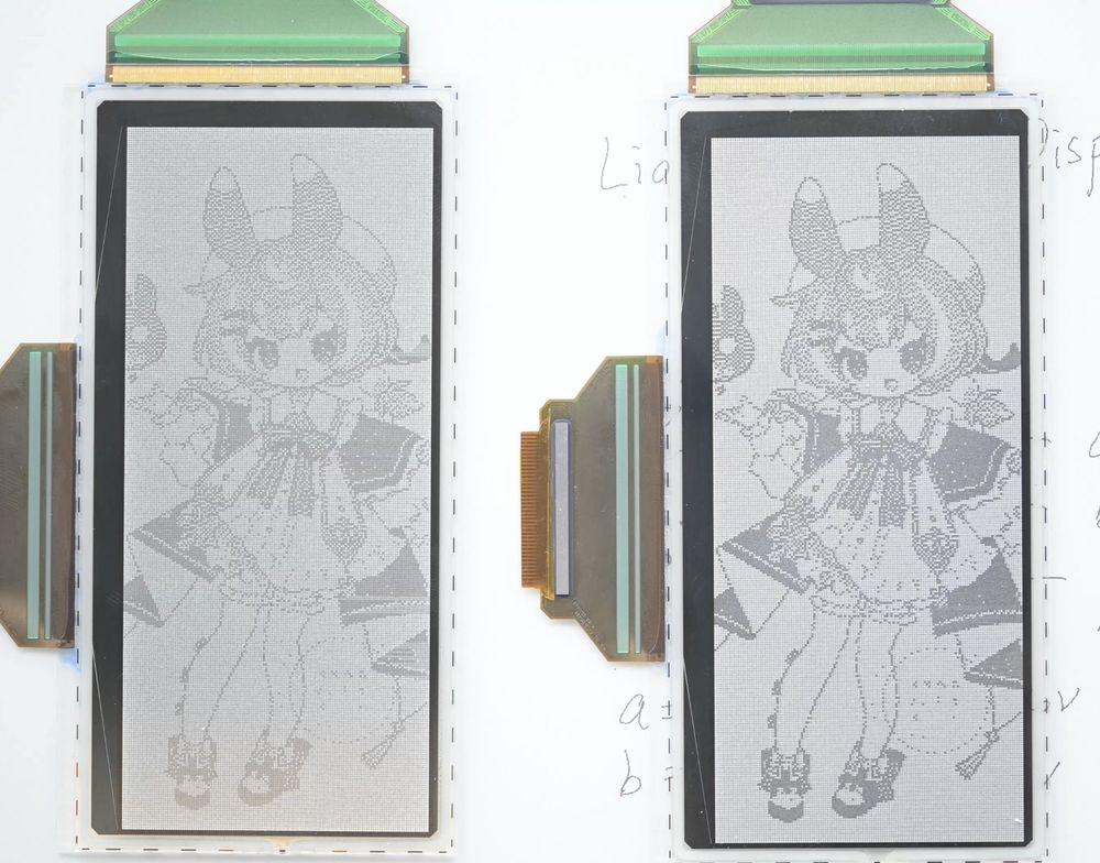
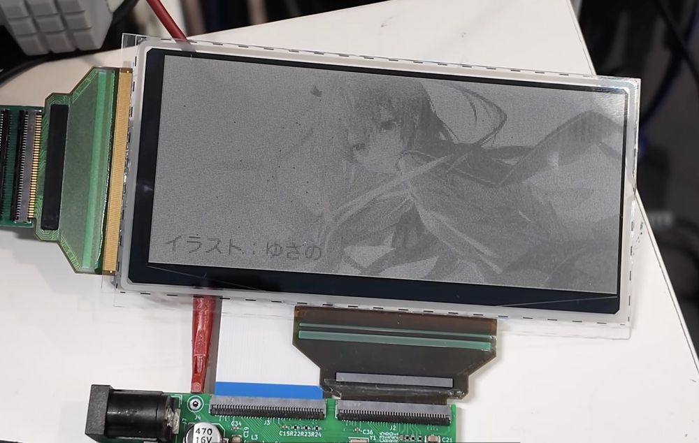
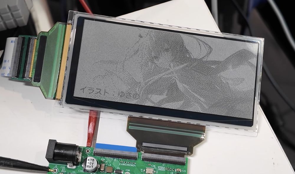
Turns out this is a very effective measure for improving the contrast. Left is with 60V/30V, while the right is with 48V/32V/16V:
April 6, 2025 at 12:22 AM
Turns out this is a very effective measure for improving the contrast. Left is with 60V/30V, while the right is with 48V/32V/16V:
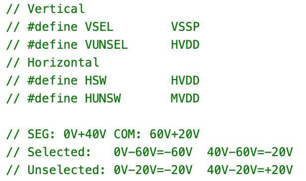
What I ended up realizing is, there is no requirement that I have to provide two STV7733 with the same voltage. By giving the H/V different voltages (specifically 60V/40V/20V), the voltage on the non-selected pixels are reduced to 20V while keeping the 60V for selected pixels.
April 6, 2025 at 12:21 AM
What I ended up realizing is, there is no requirement that I have to provide two STV7733 with the same voltage. By giving the H/V different voltages (specifically 60V/40V/20V), the voltage on the non-selected pixels are reduced to 20V while keeping the 60V for selected pixels.
I can reduce the voltage to say, 60V/30V, this reduces the non-selected pixel voltage down to 30V, but also reduces the selected pixel voltage down to 60V. There are some limited improvements by doing so.
April 6, 2025 at 12:21 AM
I can reduce the voltage to say, 60V/30V, this reduces the non-selected pixel voltage down to 30V, but also reduces the selected pixel voltage down to 60V. There are some limited improvements by doing so.
Unless there is a way to improve the contrast... The main reason for the contrast loss is the from the non-selected voltage I mentioned previously: Pixels that shouldn't be driven are still subject to a 40V voltage difference. This is more than enough to get the pixels moving
April 6, 2025 at 12:20 AM
Unless there is a way to improve the contrast... The main reason for the contrast loss is the from the non-selected voltage I mentioned previously: Pixels that shouldn't be driven are still subject to a 40V voltage difference. This is more than enough to get the pixels moving
The paper mentioned it's possible to do greyscale on the screen, so I tried that as well. It works by not driving the pixel all the way. I tried only up to 8 levels of greyscale. I think higher is possible, but with the poor contrast, it won't make too much of a difference.
April 6, 2025 at 12:20 AM
The paper mentioned it's possible to do greyscale on the screen, so I tried that as well. It works by not driving the pixel all the way. I tried only up to 8 levels of greyscale. I think higher is possible, but with the poor contrast, it won't make too much of a difference.
And this is how it looks after some trial and error:
April 6, 2025 at 12:19 AM
And this is how it looks after some trial and error:
Another thing to know is that, according to the paper, it's also better to use a bunch of short pulses instead of a single long pulse.
April 6, 2025 at 12:19 AM
Another thing to know is that, according to the paper, it's also better to use a bunch of short pulses instead of a single long pulse.
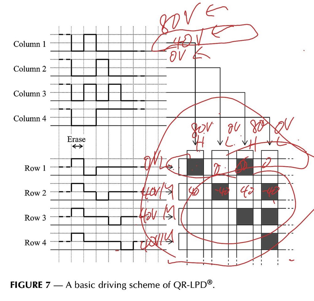
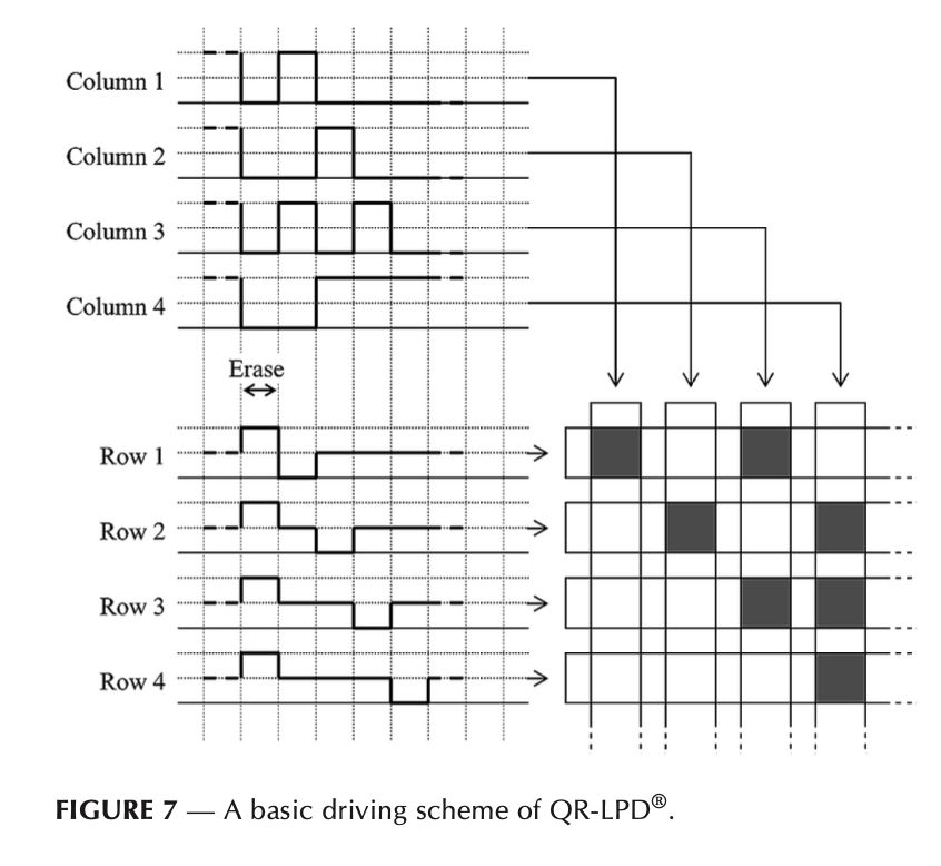
This means other than the selected line, we also need to consider pixels on the none selected line. In this scheme, still assuming the 80V and 40V driving voltage, the selected pixel would see a 80V voltage, while the non-selected pixel would still see a 40V voltage.
April 6, 2025 at 12:19 AM
This means other than the selected line, we also need to consider pixels on the none selected line. In this scheme, still assuming the 80V and 40V driving voltage, the selected pixel would see a 80V voltage, while the non-selected pixel would still see a 40V voltage.
The paper comes to the rescue again, it provides a basic driving scheme. Just like on an LED matrix, only one line is selected at a time, and the segments are set based on the pixel of that line. Unlike LED, the LPD responds to both positive and negative voltage
April 6, 2025 at 12:18 AM
The paper comes to the rescue again, it provides a basic driving scheme. Just like on an LED matrix, only one line is selected at a time, and the segments are set based on the pixel of that line. Unlike LED, the LPD responds to both positive and negative voltage
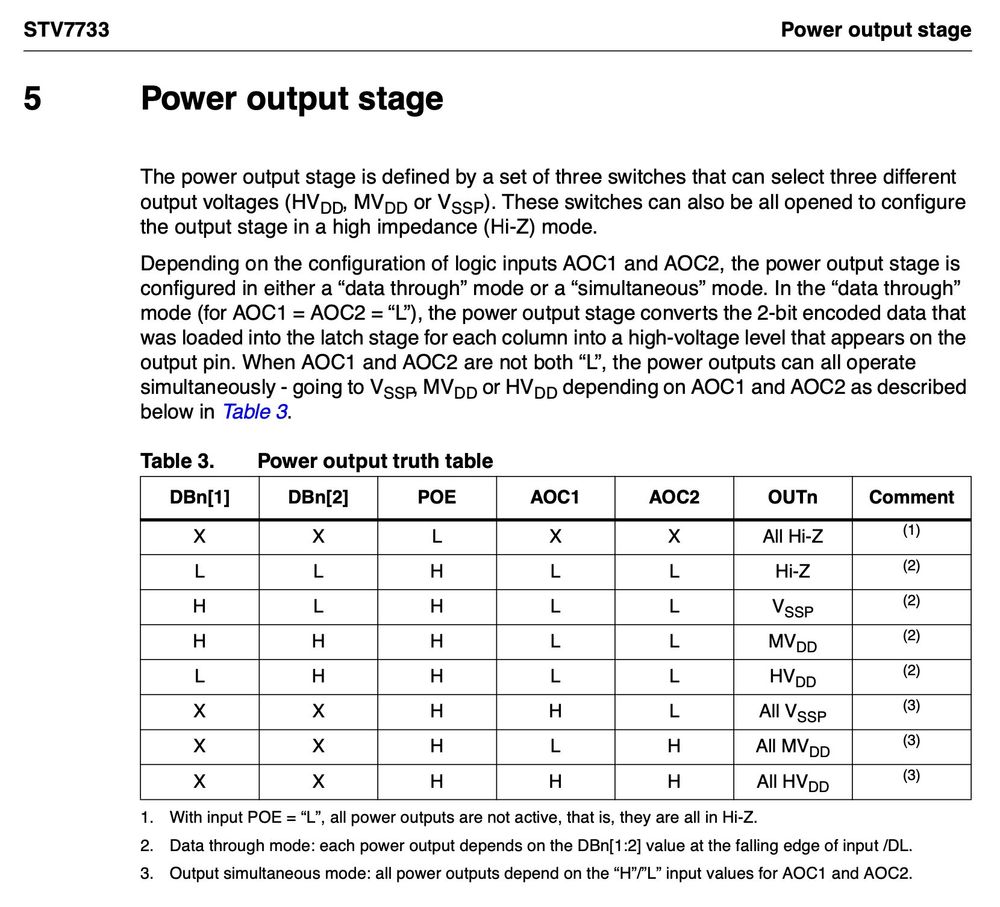
On to the software. The STV7733 used on this screen is essentially a giant high voltage shift register. It does nothing other than outputting a lot of specified voltages. So driving it actually requires synthesizing the driving waveform by the MCU.
April 6, 2025 at 12:18 AM
On to the software. The STV7733 used on this screen is essentially a giant high voltage shift register. It does nothing other than outputting a lot of specified voltages. So driving it actually requires synthesizing the driving waveform by the MCU.
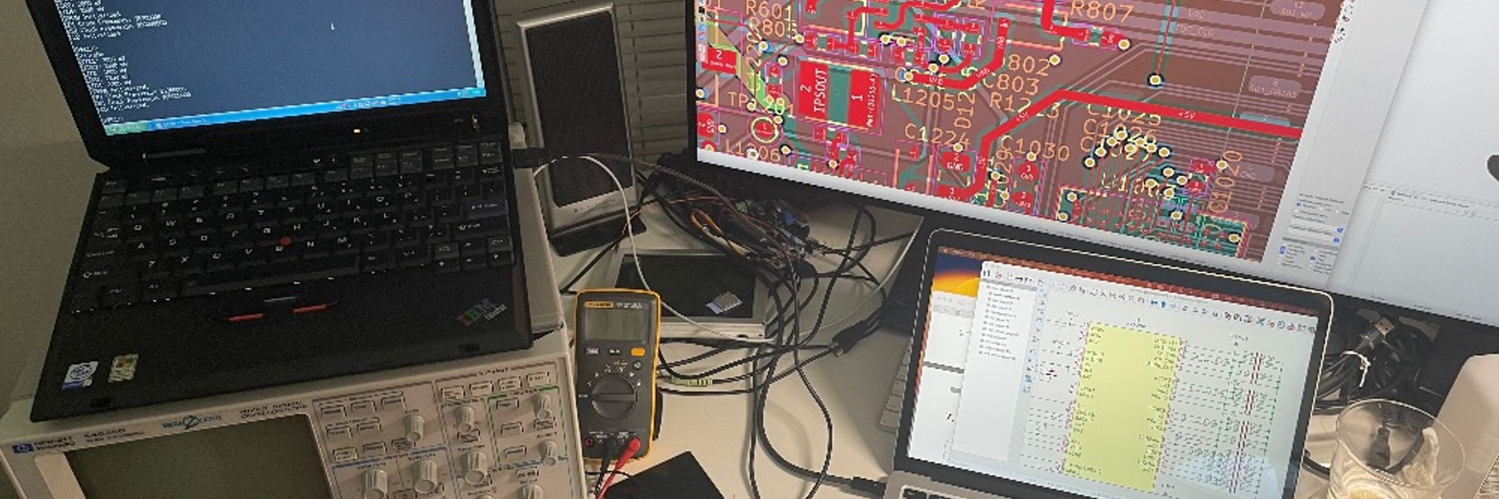
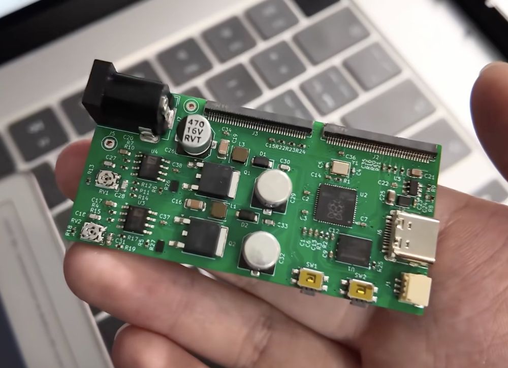
With the pinout I can finally design the board. Here is what I got. It has got 2 boost converters to generate the 40V and 80V needed for driving the screen (at least the paper says these two voltages), and a RP2040 for generate all the timings.
April 6, 2025 at 12:18 AM
With the pinout I can finally design the board. Here is what I got. It has got 2 boost converters to generate the 40V and 80V needed for driving the screen (at least the paper says these two voltages), and a RP2040 for generate all the timings.
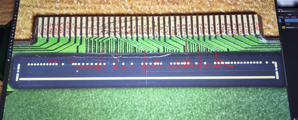
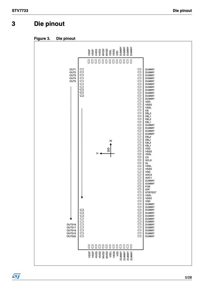
So what I did is I did an overlay of the bump map in the datasheet on top of the packaged COF. In this way I can deduce the pinout of the COF:
April 6, 2025 at 12:17 AM
So what I did is I did an overlay of the bump map in the datasheet on top of the packaged COF. In this way I can deduce the pinout of the COF:
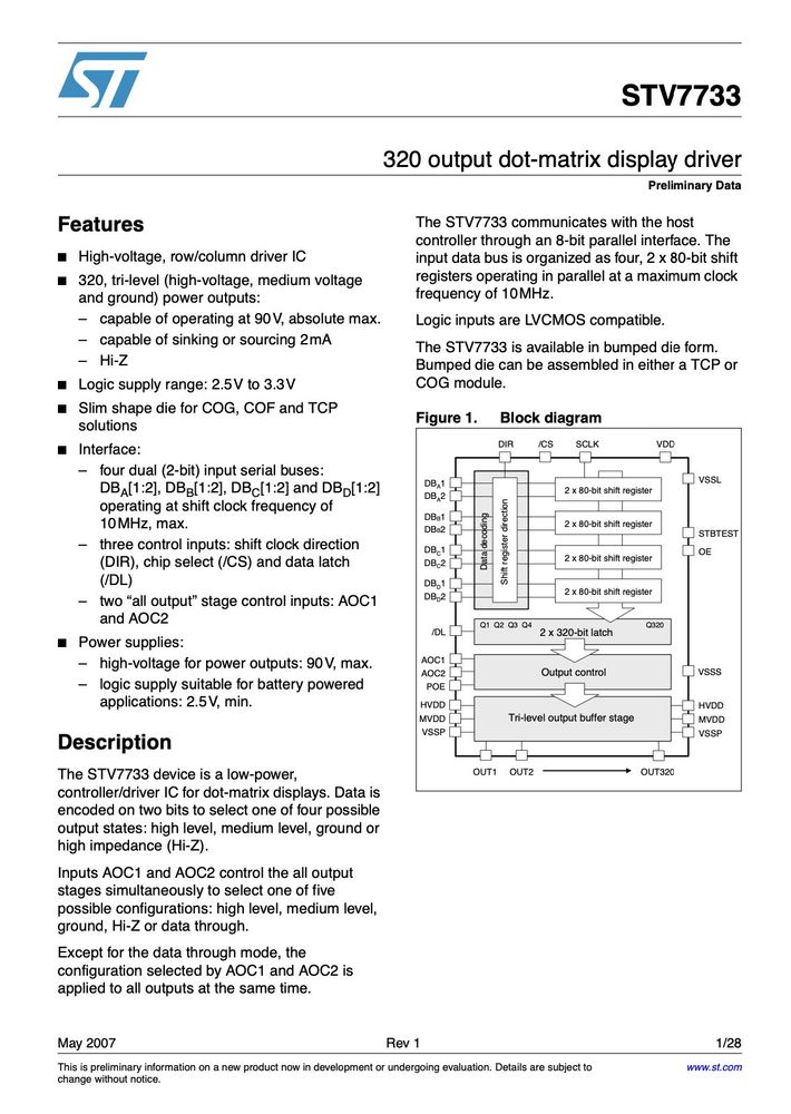
Even better, ST still has the datasheet publicly available on their website. The bad part is, the datasheet is for the gold bumped chip only, not the COF. So I still don't know the pinout of the COF on the screen.
April 6, 2025 at 12:17 AM
Even better, ST still has the datasheet publicly available on their website. The bad part is, the datasheet is for the gold bumped chip only, not the COF. So I still don't know the pinout of the COF on the screen.
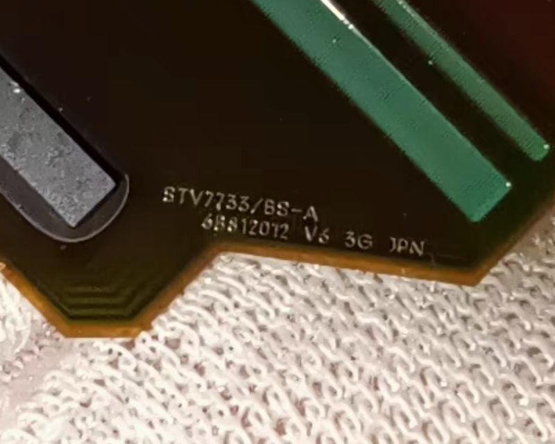
To drive the screen, I will need to know the pinout of the thing. Luckily, COF chips usually have their model number marked on them somewhere. This one is of no exception:
April 6, 2025 at 12:16 AM
To drive the screen, I will need to know the pinout of the thing. Luckily, COF chips usually have their model number marked on them somewhere. This one is of no exception:
Back to the screen I got, I have some clue about its original use: electronic shelf labels (ESL). Specifically, I suspect it was used on the Pricer DotMatrix(TM) ESLs from around 2008. Here is a video showing the thing, though I am not super confident.
www.youtube.com/watch?v=6JNO...
www.youtube.com/watch?v=6JNO...

Linking DotMatrix Labels in Supermarket
YouTube video by PricerAB
www.youtube.com
April 6, 2025 at 12:16 AM
Back to the screen I got, I have some clue about its original use: electronic shelf labels (ESL). Specifically, I suspect it was used on the Pricer DotMatrix(TM) ESLs from around 2008. Here is a video showing the thing, though I am not super confident.
www.youtube.com/watch?v=6JNO...
www.youtube.com/watch?v=6JNO...