


@adafruit-playground.com


Your own TTS engine for the Fruit Jam Spell Jam app

Your own TTS engine for the Fruit Jam Spell Jam app
Overview
The Spell Jam app on the Fruit Jam is a twist on a classic electronic toy. Check out the Spell Jam learn guide to learn all about it.
By default, Spell Jam uses the Amazon Polly Text-to-Speech (TTS) service to create audio from the entered text. While Amazon's service can be used for free during a trial period, it does require an AWS account.
If you'd prefer not to create an Amazon AWS account, you can instead run a local TTS server on your home network using open-source models like KittenTTS or Kani-TTS.
This playground will walk you through the steps required to run a local TTS server on your network and configure Spell Jam on your Fruit Jam to use that server instead of AWS.
Installing a Text-to-Speech Model
There are two TTS AI models that the Spell Jam local backend currently works with:
KittenTTS - lightweight, will run on a Raspberry Pi 4/5
Kani-TTS - newer, but may require an Nvidia GPU.
adafruit-playground.com
October 16, 2025 at 1:19 PM
Your own TTS engine for the Fruit Jam Spell Jam app
Magnetometer - MMC5603 to measure gas usage inside your home with home assistant

Magnetometer - MMC5603 to measure gas usage inside your home with home assistant
I wanted to measure the gas usage inside my home and push the data into Home Assistant.
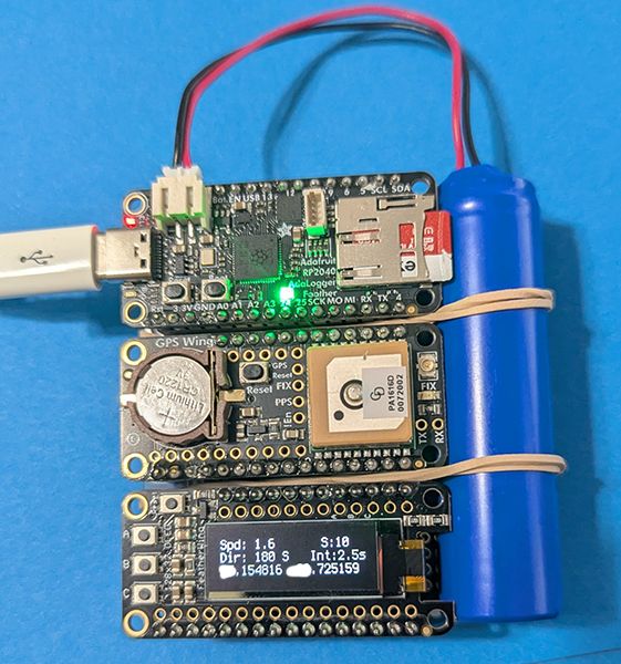
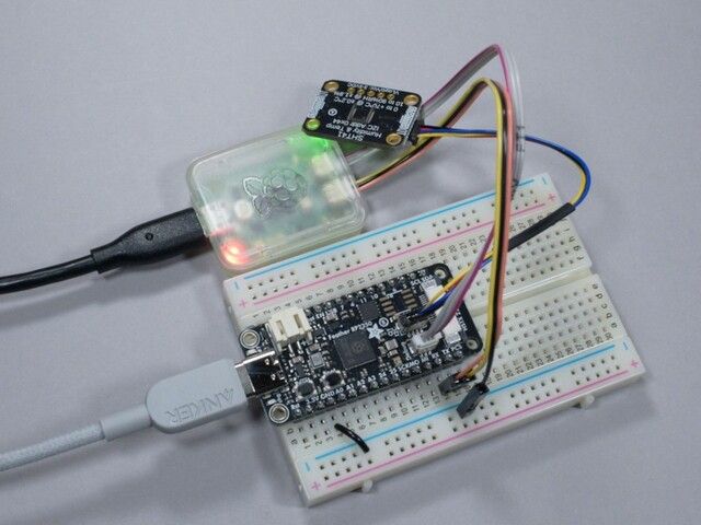
To collect the data, I wanted to use the MMC5603 magnetometer + ESP32 Feather V2. The MMC5603 had a great price point and the ESP32 Feather V2 was able to connect to my Home Assistant server via WiFi.
Requirements
ESPHome 2025.8.3
The Adafruit Products above (MMC5603 + ESP32 Feather V2 or similar board that can connect via WiFi)
Ethernet Cable (Cat 5 and later is fine)
USB Power Adapter (e.g. like this one , 5V 1A)
A short USB-A to USB-C connector (e.g. like this one, data isn't important here - so any cable will do)
M2.5 screws (lengths and materials will be up to you, I used nylon M2.5 screws to attach the bracket to the gas meter and metal M2.5 screws for the MMC5603 to the bracket).
If you end up using any earlier version of ESPHome and you'll run into issues like I did where the MMC5603 wasn't being registered properly.
I connected everything like this diagram:
Assembly
adafruit-playground.com
October 16, 2025 at 1:18 PM
Magnetometer - MMC5603 to measure gas usage inside your home with home assistant
Busy Buttons - noisy glowy buttons for babies and toddlers

Busy Buttons - noisy glowy buttons for babies and toddlers
I had a collection of spare parts from Adafruit laying around. My toddler loves mashing buttons, particularly ones that make noise, so I decided to turn those spare parts into something they'd enjoy. As for my own sanity, it'll diminish as the sounds play relentlessly, but I built in a secret "mute" cheat code. I used Adafruit's arcade buttons which can withstand a lot of toddler smashing and used a massive battery so it'll almost never need charging.
You can view more about the project on Printables and see the source code and instructions on GitHub to make your own. The enclosure is 3D printed and the software runs on an ESP32-S2 Feather with CircuitPython.
As a much more advanced project, I also created BabyPod: an interface to Baby Buddy written in a lot of CircuitPython.
adafruit-playground.com
September 16, 2025 at 4:11 PM
Busy Buttons - noisy glowy buttons for babies and toddlers
A Neopixel Floor Lamp with a Twist

A Neopixel Floor Lamp with a Twist
This is probably the coolest thing I have built with Adafruit electronics! When I viewed the learn guide describing the Floor Lamp with NeoPixels and WLED Custom Animations by Erin St Blaine I knew that I just had to build this work of art. I tend to like building things with wood, so my adaption of Erin's design for the most part replaces some elements with wood structures. I was pleasantly surprised with the results!
Many of the instructions that I provide below leverage Erin's design and construction. You will need to refer to Erin's learn guide frequently as you follow the instructions below.
adafruit-playground.com
September 2, 2025 at 3:22 PM
A Neopixel Floor Lamp with a Twist
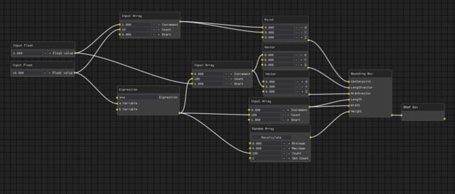
Countdown Complete: It's finally here! 🎉 Upgraded Actions on IO - How to do Math(ematics)
Countdown Complete: It's finally here! 🎉 Upgraded Actions on IO - How to do Math(ematics)
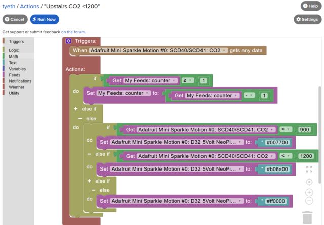
Blockly has been slowly worming it's way into Adafruit IO, with a first edition replicating the old Action forms. Now the latest release brings the wealth of features we've been dreaming of, allowing great complexity!
Will you be the first to bring down the house of cards/servers? Let us know in the forums if you do (or run into other issues)! Let's start off with something simple, how to subtract one from a feed value (as a countdown)...
We'll explore a quick yet complex multi-action example, changing LED colour based on air quality, and additionally a Utility Light mode using the onboard button to request 30seconds of Bright White Light (useful in a kitchen).
Setup a Wippersnapper device
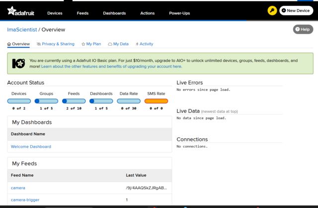
Adafruit IO has a devices page, which shows the special "Wippersnapper" devices, these run the arduino firmware that allows wifi connected boards to easily connect and configure components (inputs/outputs/sensors) with no code. Each component then has associated feeds for interacting with, so using the on board button becomes child's play.
Install wippersnapper, you're best off finding the learn guide for your board and then locate the Wippersnapper pages. Alternatively there is a quick start guide, or just do the usual hacky thing and have a go with no prior knowledge...
Visit this link (https://io.adafruit.com/devices/new) when signed in to be taken to the New Device setup page, then select your board and follow the onscreen instructions. (You need an IO page open when the board first connects to accept the registration request).
adafruit-playground.com
May 1, 2025 at 3:34 PM
Countdown Complete: It's finally here! 🎉 Upgraded Actions on IO - How to do Math(ematics)
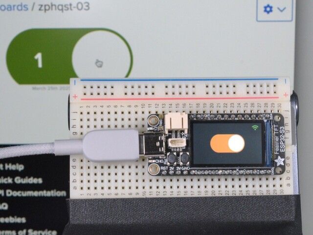
The Many Possibilities of Adafruit IO Actions and an Arcade Button
The Many Possibilities of Adafruit IO Actions and an Arcade Button
Overview
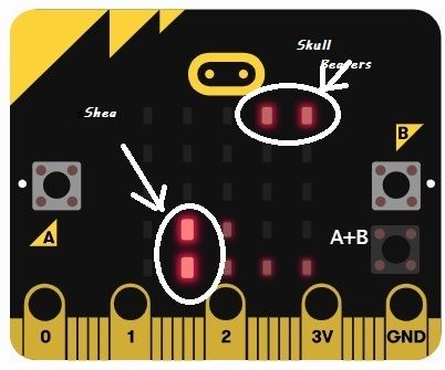
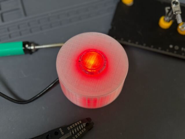
As we get closer to launching the new Adafruit IO Actions, it has been fun thinking of the many fun ways it can be used. Here is a really simple project that has a ton of potential without writing a single line of code. With this project, I simply added a NeoPixel to a simple arcade button (using the below Learn guide), and then use that LED and button to communicate information in different ways. The more I play around with this project, the more ideas I come up with. So be sure to check back here often as I will post more ideas as I come up with them.
Parts Used
I used the NeoPixel Mini Button as shown in the guide above, but used the QT Py ESP32-S3 board with the NeoPixel BFF to drive the NeoPixel, then just soldered one side of the button to 3V on the QT Py, and the other side of the button to A2.
You could also simply skip modifying the arcade button, and just use the built in NeoPixel on the QT Py. You could even just use the built in pushbutton on the QT Py and skip the Arcade Button all together. This guide isn't so much about the specific project, as it is about the possibilities of the new Adafruit IO Actions. You can set this up with any NeoPixel and button.
With that in mind, here are the products I used:
adafruit-playground.com
April 21, 2025 at 11:13 AM
The Many Possibilities of Adafruit IO Actions and an Arcade Button
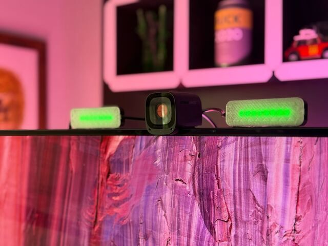
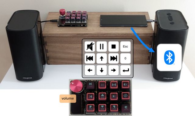
🎵️ Media hub 2.0: Media control w/opt Bluetooth
🎵️ Media hub 2.0: Media control w/opt Bluetooth
Overview
Physical controls for a more enjoyable media playback experience.
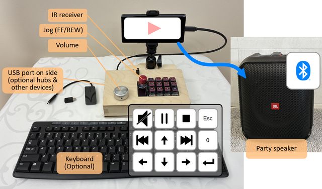
Features
Responsive volume knob & mute button.
Transport controls (play/pause, stop, FF/REW, skip tracks).
Pair up with your favourite Bluetooth® speakers.
Quick, physical connection (don't have to go through menu system to pair with keypad & speakers).
Customizable controls/scheme.
This project tries to improve over the original "Media hub" presented here.
More compact design
Bigger volume knob - not interfering with macropad keys.
🛒️List of main material/hardware
(See section "More tools/materials/hardware" near the end of this note for extras)
adafruit-playground.com
April 1, 2025 at 1:57 PM
🎵️ Media hub 2.0: Media control w/opt Bluetooth
Zephyr Quest: IoT Toggle Switch for Feather TFT
Zephyr Quest: IoT Toggle Switch for Feather TFT
Overview
This guide shows how to make an IoT toggle switch with an Adafruit Feather TFT ESP32-S3, Zephyr, and Adafruit IO. Key features include: GPIO input for Boot button, LVGL graphics, MQTT over WiFi with TLSv1.2, and USB serial shell commands for saving WiFi and MQTT configuration settings to NVM flash. This guide is intended for people who want to learn how to write applications in C using Zephyr APIs.
Demo video: IoT toggle switch: Zephyr + Feather TFT + Adafruit IO
adafruit-playground.com
March 28, 2025 at 3:56 PM
Zephyr Quest: IoT Toggle Switch for Feather TFT
Zephyr Quest: ST7789 Display with Feather RP2350
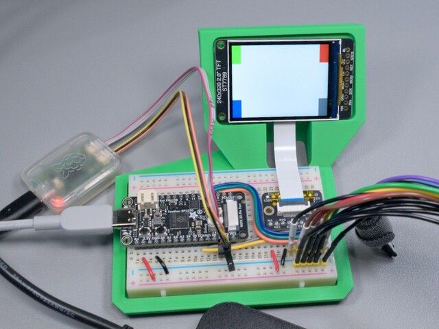
Zephyr Quest: ST7789 Display with Feather RP2350
Overview
As part of a series on Zephyr with Adafruit hardware, this guide shows how to configure Zephyr to use an ST7789 TFT display with a Feather RP2350. By connecting the display with a breadboard, we can use a logic analyzer to verify that the Zephyr display driver pin configuration agrees with the CircuitPython display driver. This guide is meant for people interested in adding support for Adafruit displays to Zephyr.
adafruit-playground.com
March 3, 2025 at 3:44 PM
Zephyr Quest: ST7789 Display with Feather RP2350
Zephyr Quest: SWD Pogo Adapter for CLUE
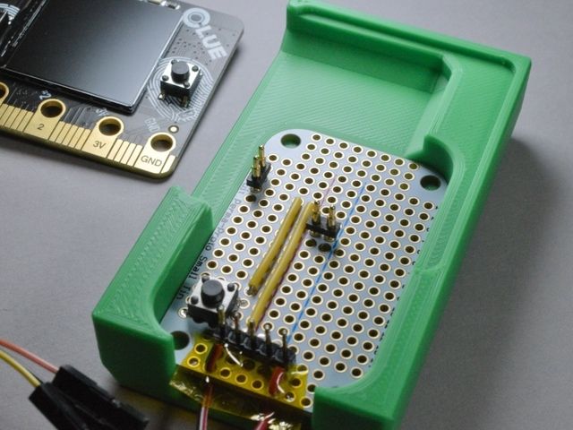
Zephyr Quest: SWD Pogo Adapter for CLUE
Overview
adafruit-playground.com
February 18, 2025 at 5:36 PM
Zephyr Quest: SWD Pogo Adapter for CLUE
Media hub: Media control w/opt Bluetooth
Media hub: Media control w/opt Bluetooth
Overview
Direct physical control for a more enjoyable media playback experience.
Features
Responsive volume knob & mute button.
Transport controls (play/pause, stop, FF/REW, skip tracks).
Pair up with your favourite Bluetooth® speakers.
Quick, physical connection (don't have to go through menu system to pair with keypad & speakers).
Customizable controls/scheme.
Customizable setup: Optionally connect USB hub/dock for added features, for example:
mirror phone to TV w/HDMI out: Watch videos on a bigger screen
add keyboard: Better typing experience for texts/emails.
Solderless project.
Main hardware
adafruit-playground.com
February 18, 2025 at 5:34 PM
Media hub: Media control w/opt Bluetooth
Zephyr Quest: Feather RP2350 Board Def
Zephyr Quest: Feather RP2350 Board Def
Overview
adafruit-playground.com
February 11, 2025 at 2:34 PM
Zephyr Quest: Feather RP2350 Board Def
Weather Display Using Open-Meteo's API
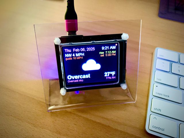
Weather Display Using Open-Meteo's API
Overview
This desktop local weather monitor is the next in the continuing quest to update John Park's original openweathermap-based PyPortal weather station project with a free weather information service that doesn't need a credit card paywall account. Thanks to some investigative work done by @DJDevon3, this latest version uses the free non-commercial Open-Meteo (OM) API service. Bonus: No account or key is required to access the API if used for non-commercial projects.
adafruit-playground.com
February 10, 2025 at 4:53 PM
Weather Display Using Open-Meteo's API
Guide: Build a 'MiniMarquee' WiFi Text Scroller
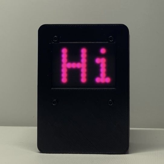
Guide: Build a 'MiniMarquee' WiFi Text Scroller
In the last few years that I've been hacking on microelectronics, one of my favorite types of project has been the humble text scroller. While these devices are usually simple to build, I've found that the process of actually getting the text onto the devices can be anything but simple!
Often, it requires the user perform one or more of the following:
Connecting the device to a computer and editing/compiling/reinstalling firmware source code
Connecting the device to your main Wi-Fi network
Using an custom-built application on your phone, or something like Adafruit's Bluefruit Connect
Making an account with some sort of IoT service (such as Adafruit IO) and/or use an MQTT server
Opening the browser and typing a strange URL in the address bar (such as an IP address)
That's a lot of work just to get some text to scroll across a screen! Especially if the text scrolling gadget is intended as a gift for a friend or family member who may not be tech savvy. It's no fun giving a gift to someone who can't figure out how to use it!
adafruit-playground.com
February 9, 2025 at 7:53 PM
Guide: Build a 'MiniMarquee' WiFi Text Scroller
Digital Clock with WiFi and Weather (Huzzah & 128x64OLED)
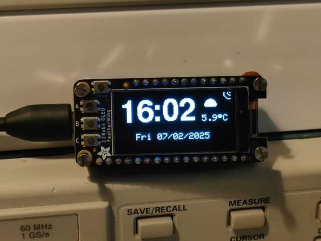
Digital Clock with WiFi and Weather (Huzzah & 128x64OLED)
I had an Adafruit Huzzah and an OLED FeatherWing 128 x 64 in my box of goodies and decided to make a smart digital clock for my study.
The clock is connected to internet via WiFi, synchronises the time and via an api displays the temperature in my area. It is set to update every 5 minutes. Also displays an icon of the current weather.
These are parsed from the api response:
{"coord":{"lon":yyyyyy,"lat":xxxxx},"weather":[{"id":800,"main":"Clear","description":"clear sky","icon":"01n"}],"base":"stations","main":{"temp":1.03,"feels_like":-1.33,"temp_min":0.57,"temp_max":2.64,"pressure":1039,"humidity":76,"sea_level":1039,"grnd_level":1034},"visibility":10000,"wind":{"speed":2.06,"deg":170},"clouds":{"all":0},"dt":1738790391,"sys":{"type":1,"id":1440,"country":"GB","sunrise":1738742403,"sunset":1738773892},"timezone":0,"id":3333224,"name":"xxxxxx City","cod":200}
adafruit-playground.com
February 7, 2025 at 5:11 PM
Digital Clock with WiFi and Weather (Huzzah & 128x64OLED)
CNC Rotary Encoder Internals
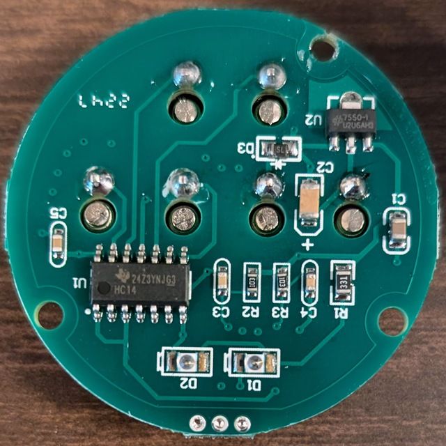
CNC Rotary Encoder Internals
I was working with one of Adafruit's CNC Rotary Encoders and made a mistake wiring. Well, long story short, I killed it. I am not sure exactly what I did, but I suspect I accidentally drove its outputs with an improper voltage.
To prevent the experience from being a total loss, I took the time to partially disassemble it.
adafruit-playground.com
February 7, 2025 at 3:25 PM
CNC Rotary Encoder Internals